
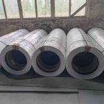
FRP(Fiberglass/GRP/PFRV) Coil/Roll
July 14, 2025
FRP Composites: Redefining the Standards for Refrigerated Truck Body Materials
May 29, 2026Selection of Composite Materials for Refrigerated Truck Bodies: Analysis of the Mechanical Properties and Process Compatibility of FRP Rolls
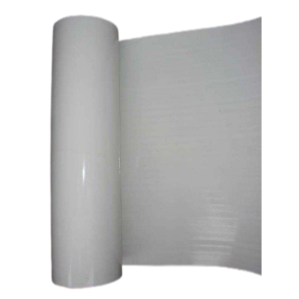
Technical Prerequisites for Material Substitution
The transition from metal skin to composite materials is not merely about weight reduction; it involves a redesign of the load path.
The failure mode of aluminum sheets is large deformation following yield, whereas the failure mode of FRP is brittle fracture due to fiber breakage. This implies that the logic of structural design must shift: from a safety factor method that allows for plastic deformation to a strain-controlled method that matches ultimate strength with elastic modulus.
The difference in tensile modulus between the longitudinal (0°) and transverse (90°) directions of our composite sheets is controlled within 15%, and the symmetry of the layup ensures that warpage after curing is ≤3 mm/m. Coachbuilders do not need to make additional mold adjustments to account for the anisotropy of composite materials; existing metal sheet forming equipment can be used directly.
Engineering Basis for Thickness Selection
1.5mm–2.0mm:Buckling Critical Load Control Zone
Failure of interior panels and partitions is typically not due to strength failure but rather local buckling. Calculated as a simply supported rectangular plate with four fixed edges, a 1.5mm FRP sandwich panel has a critical buckling stress under a uniformly distributed air pressure of 0.5 kPa that is 1.8 times that of an aluminum skin. This is attributed to the synergistic deformation between the core material’s support effect and the face sheets. This specification is suitable for areas without concentrated loads, such as the roof curves of passenger buses and the interior walls of cargo vans. The layup design primarily uses 0°/90° orthogonal orientations to minimize diagonal shear deformation.
2.5mm–3.0mm: Impact Toughness-Dominated Zone
The outer skin must pass the 30 J ball-impact test specified in ISO 6487.
The 3 mm specification maintains 72% of its impact strength at -40°C, whereas aluminum alloy drops to 45% under the same conditions.
The fiber volume fraction is controlled between 38% and 42%, and a 0.15 mm resin-rich layer forms a surface toughness buffer zone to prevent interlaminar delamination caused by stone impacts.
5.0mm: Local Compression and Bolt Load-bearing Zone
The failure mode at the bottom panel and hinge mounting surfaces is squeezing failure at the bolt hole edges. The 5mm specification employs alternating layers of unidirectional fiber (0°) and mat layers, achieving a squeezing strength of 180 MPa at the hole edges, which meets the requirement for 500,000 cyclic loads under an M10 bolt with an 8.8-grade preload.
No additional metal sleeves are required, reducing the risk of electrochemical corrosion at dissimilar material interfaces.
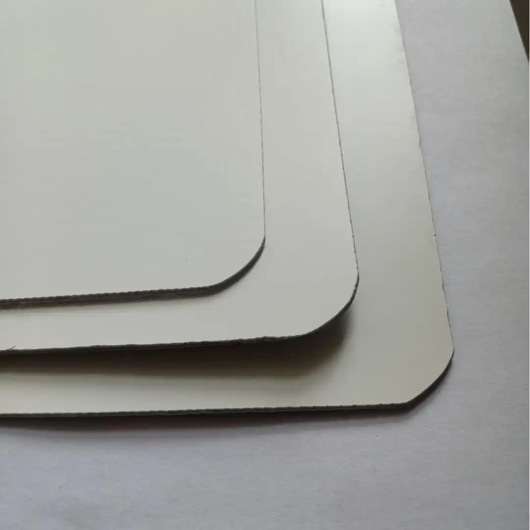
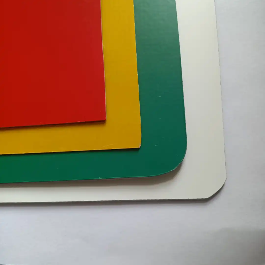
Quantitative Elimination of Thermal Bridge Effects
Hidden energy consumption in metal vehicle bodies stems from thermal bridges in the frame.
Taking a 9.6-meter refrigerated truck as an example, the peak heat flux density at the riveted joints between aluminum alloy longitudinal beams and the skin reaches 12 times that of the entire wall panel. At the riveted joints between FRP skin and steel frames, due to differences in thermal conductivity (FRP approx. 0.3 W/m·K, aluminum 237 W/m·K), the peak heat flux density drops to 1.8 times.
An even more critical improvement lies in the bonded joints. Replacing riveting with polyurethane structural adhesive completely eliminates thermal bridges while maintaining a shear strength of ≥8 MPa. Our WR series surface coating has been tested for surface energy compatibility with mainstream truck body adhesives using a dyne pen; the 38–42 mN/m range ensures stable bond peel strength.
The Unique Advantages of FRP Sheets in Cold Chain Truck Bodies
Controllable Design Flexibility Through Anisotropy
Metal sheets have consistent properties in all directions, which means you cannot optimize the material to address the specific stress characteristics of the truck body. With FRP, the layup angles can be designed: 0° layers in the longitudinal direction bear bending stresses in the direction of travel, ±45° layers suppress torsional shear, and 90° layers control lateral contraction. Since the side panels of the cargo compartment are primarily subjected to wind pressure and lateral compression from cargo, we adjust the proportion of 0° layers to 60%, increasing longitudinal stiffness without increasing surface density. The roof panel, which bears negative pressure and snow loads, has an increased proportion of chopped strand mat layers, boosting interlaminar shear strength by 20%. This type of directional design cannot be achieved with metal panels.
Damage Tolerance and Repairability
Repairing dents in metal skins requires panel pulling, body filler leveling, and spray painting followed by baking, taking 4–6 hours per location. Additionally, the paint film thickness in the repaired area is uneven, posing a high risk of peeling later on. Impact damage to FRP laminates typically involves resin cracking or shallow fiber fractures. If the damage does not penetrate the load-bearing layer, the affected area is sanded down to expose intact fibers, a prepreg patch of the same specifications is applied, and the repair is sanded smooth after curing at room temperature or under heat. This process takes 1–2 hours per location. After repair, mechanical properties are restored to over 85% of the original strength, and there is no need to match the original factory paint finish; the matte or rough surface can be painted over directly.
Thermal Expansion Coefficient Compatibility
The summer bulging and winter shrinkage cracks in metal vehicle bodies result from the thermal expansion difference between aluminum panels (23×10⁻⁶/°C) and steel frames (12×10⁻⁶/°C). The longitudinal thermal expansion coefficient of FRP (6–10×10⁻⁶/°C) is similar to that of steel. During temperature cycling from -40°C to 80°C, displacement at bonded or riveted joints is coordinated, reducing shear fatigue in the adhesive layer. When combined with an XPS foam core (50×10⁻⁶/°C), the FRP facing constrains the core’s expansion, preventing high-temperature blistering. This thermal compatibility ensures the vehicle compartment maintains airtightness even in extreme temperature zones, resulting in stable cold engine start-stop frequency.